
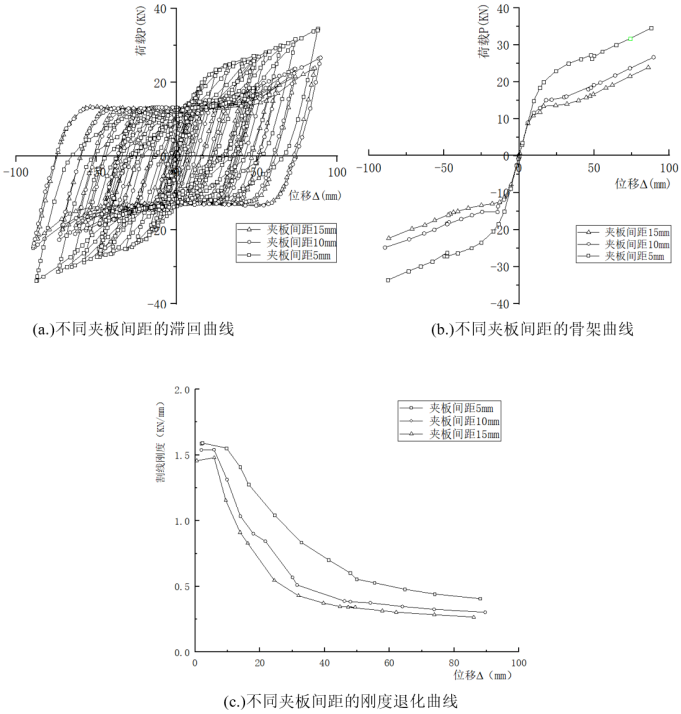
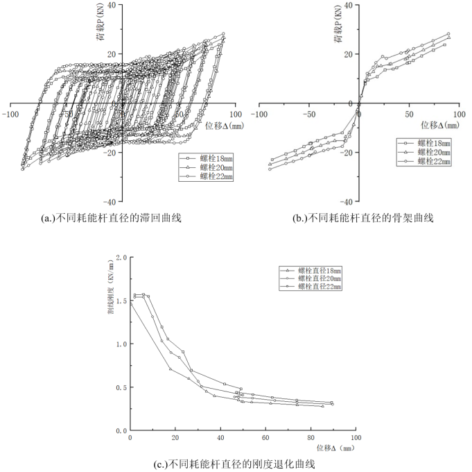
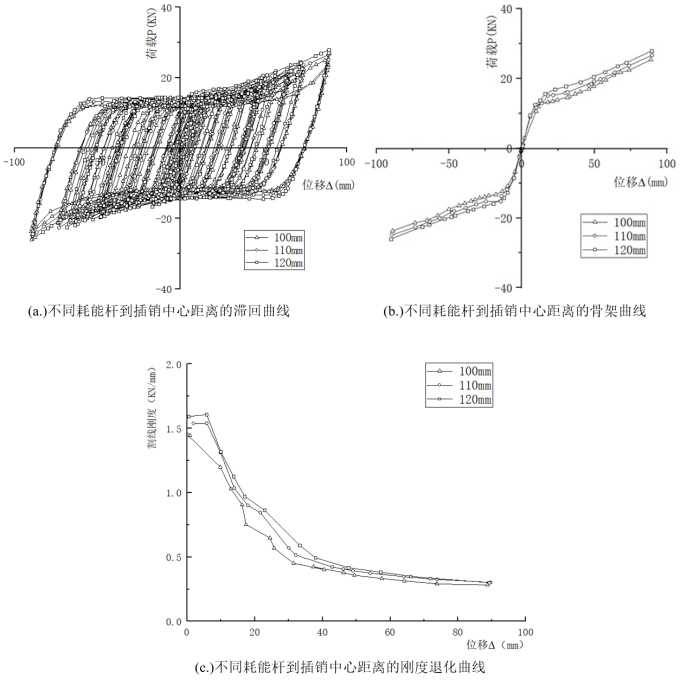
To improve the hysteretic performance of prefabricated beam-column connections, a parametric analysis is conducted on an energy-dissipating damper connection composed of shear rods and a pin shaft. Based on the finite element method, the effects of the gusset plate spacing, the diameter of the energy-dissipating rods, and the distance from the rods to the pin shaft center on the seismic performance of the connection are investigated. The results indicate that increasing the rod diameter significantly enhances both the load-bearing capacity and ductility. When the rod diameter is increased from 18 mm to 22 mm, the peak load-bearing capacity increases by 18.5%, and the ductility coefficient improves by 27.7%. Increasing the gusset plate spacing enhances the energy dissipation capacity, but the peak load-bearing capacity decreases by up to 39.7%. Increasing the distance from the rods to the pin shaft center simultaneously improves the load-bearing capacity and stiffness; when this distance is increased from 100 mm to 120 mm, the load-bearing capacity increases by 10.0%. It is recommended to prioritize the use of 22 mm diameter rods and a center distance of 120 mm, while the gusset plate spacing should be selected between 5 mm and 15 mm according to the seismic fortification intensity. The optimized damper can effectively improve the seismic performance of the connection.
| Published in | Science Research (Volume 14, Issue 4) |
| DOI | 10.11648/j.sr.20261404.20 |
| Page(s) | 210-217 |
| Creative Commons |
This is an Open Access article, distributed under the terms of the Creative Commons Attribution 4.0 International License (http://creativecommons.org/licenses/by/4.0/), which permits unrestricted use, distribution and reproduction in any medium or format, provided the original work is properly cited. |
| Copyright |
Copyright © The Author(s), 2026. Published by Science Publishing Group |
Energy Dissipation Damper, Finite Element Analysis, Parameter Optimization, Seismic Behavior
4.8级剪杆 | Q345钢 | ||
|---|---|---|---|
屈服应力(MPa) | 塑性应变 | 屈服应力(MPa) | 塑性应变 |
320 | 0 | 345.57 | 0 |
325.86 | 0.01813 | 351.9 | 0.01813 |
407.29 | 0.13659 | 667 | 0.13659 |
425 | 0.17901 | 696 | 0.17901 |
378.59 | 0.21216 | 620 | 0.21216 |
试件编号 | 夹板间距(mm) | 耗能杆直径(mm) | 耗能杆到插销中心距(mm) |
|---|---|---|---|
N1 | 10 | 20 | 110 |
N2 | 10 | 20 | 110 |
N3 | 15 | 20 | 110 |
N4 | 10 | 18 | 110 |
N5 | 10 | 22 | 110 |
N6 | 10 | 20 | 100 |
N7 | 10 | 20 | 120 |
夹板间距(mm) | 等效屈服力(KN) | 等效屈服位移(mm) | 峰值承载力(KN) | 峰值位移(mm) | 延性系数 | 极限承载力(kN) | 极限承载位移(mm) |
|---|---|---|---|---|---|---|---|
5 | 27.32 | 48.51 | 34.13 | 87.70 | 1.82 | 29.01 | 87.70 |
10 | 22.45 | 69.07 | 25.78 | 89.45 | 1.30 | 21.91 | 89.45 |
15 | 20.04 | 70.40 | 22.73 | 86.58 | 1.23 | 19.32 | 86.58 |
夹板间距(mm) | 等效屈服力(KN) | 等效屈服位移(mm) | 峰值承载力(KN) | 峰值位移(mm) | 延性系数 | 极限承载力(kN) | 极限承载位移(mm) |
|---|---|---|---|---|---|---|---|
18 | 21.02 | 72.64 | 23.39 | 86.19 | 1.19 | 19.88 | 86.19 |
20 | 23.63 | 73.64 | 26.68 | 89.61 | 1.22 | 22.68 | 89.61 |
22 | 22.81 | 58.82 | 27.57 | 89.25 | 1.52 | 23.43 | 89.25 |
耗能杆到插销中心距离(mm) | 等效屈服力(KN) | 等效屈服位移(mm) | 峰值承载力(KN) | 峰值位移(mm) | 延性系数 | 极限承载力(kN) | 极限承载位移(mm) |
|---|---|---|---|---|---|---|---|
100 | 21.29 | 69.66 | 24.52 | 88.75 | 1.28 | 20.84 | 88.75 |
110 | 22.45 | 69.07 | 25.78 | 89.45 | 1.30 | 21.91 | 89.45 |
120 | 22.96 | 66.10 | 26.97 | 89.58 | 1.36 | 22.92 | 89.58 |
| [1] | 葛琪, 李有杰, 熊峰, 等. 新型带可更换耗能装置预制混凝土梁-柱节点抗震性能分析 [J]. 工程力学, 2024, 41(S1): 57-65. |
| [2] | 童超, 吴京, 韩建平, 等. 带可更换耗能连接的装配式梁柱节点受弯承载能力试验研究及理论分析 [J]. 工程力学, 2025, 42(10): 33-42+89. |
| [3] | 杜永峰, 李芳玉, 李虎, 等. 装配式可更换分级屈服耗能连接集成形状优化及试验研究 [J]. 工程力学, 2024, 41(6): 164-176. |
| [4] | 邢国华, 王志萌, 秦拥军, 黄娇, 范玺. 新型装配式混凝土框架节点抗震性能试验研究 [J]. 土木工程学报, 2023, 56(2): 23-33. |
| [5] | 申允, 夏成建, 陈强, 王昊祥. 基于转动摩擦铰阻尼器的干式装配梁-柱节点抗震性能试验 [J]. 地震研究, 2024, 47(1): 105-113. |
| [6] | 许高娲, 周翔子, 欧进萍. 转动摩擦-弯曲屈服两级耗能阻尼器疲劳性能 [J]. 工程力学, 2026, 43(1): 85-96. |
| [7] | 洪锦雄, 周云, 列文琛, 等. 转动铅黏弹阻尼器有限元模拟分析 [J]. 建筑结构, 2025, 55(23): 98-101. |
| [8] | 张健新, 原伟涛, 戎贤. 承载-双阶耗能装配式混凝土框架节点抗震性能试验研究 [J]. 建筑结构学报, 2025, 46(1): 86-97. |
| [9] | 陈云, 陈超, 等. 装配式自复位梁柱摩擦耗能节点抗震性能研究 [J]. 建筑结构学报, 2024, 45(2): 78-87. |
| [10] | 和海芳, 周雨龙, 伍敏, 等. 基于SMA连接的装配式梁柱钢节点滞回性能数值研究 [J]. 工程力学, 2023, 40(S): 283-288. |
| [11] | 吴从晓, 列文琛, 吴昌根, 等. 装配式减震节点转动型阻尼器抗震性能及恢复力模型研究 [J]. 工程力学, 2023, 40(2): 112-122. |
| [12] | 徐秀凤, 孔子昂, 孙伟, 等. T形钢制耗能铰阻尼器抗震性能及力学模型研究 [J]. 地震工程与工程振动, 2024, 44(4): 136-147. |
| [13] | RU Y C, HE L S. Seismic behavior of a self-centering beam-to-column joint using low-yield arc steel plates for dissipating energy [J]. Journal of Building Engineering, 2024, 95: 110117. |
| [14] | 熊进刚, 王雨辰, 秦汕, 等.装配式RCS框架-屈曲约束支撑组合结构抗震性能研究 [J]. 自然灾害学报, 2023, 32(6)162-174. |
| [15] | 刘学春, 金博文, 陈学森, 等.装配式钢结构梁柱支托式螺栓连接节点抗震性能研究 [J]. 建筑结构, 2025, 55(5)9-15. |
APA Style
Zhang, T., Li, B., Ling, Y. (2026). Parametric Analysis on the Hysteretic Behavior of an Energy Dissipation Damper. Science Research, 14(4), 210-217. https://doi.org/10.11648/j.sr.20261404.20
ACS Style
Zhang, T.; Li, B.; Ling, Y. Parametric Analysis on the Hysteretic Behavior of an Energy Dissipation Damper. Sci. Res. 2026, 14(4), 210-217. doi: 10.11648/j.sr.20261404.20
@article{10.11648/j.sr.20261404.20,
  author = {Tianjing Zhang and Benben Li and Yu Ling},
  title = {Parametric Analysis on the Hysteretic Behavior of an Energy Dissipation Damper},
  journal = {Science Research},
  volume = {14},
  number = {4},
  pages = {210-217},
  doi = {10.11648/j.sr.20261404.20},
  url = {https://doi.org/10.11648/j.sr.20261404.20},
  eprint = {https://article.sciencepublishinggroup.com/pdf/10.11648.j.sr.20261404.20},
  abstract = {To improve the hysteretic performance of prefabricated beam-column connections, a parametric analysis is conducted on an energy-dissipating damper connection composed of shear rods and a pin shaft. Based on the finite element method, the effects of the gusset plate spacing, the diameter of the energy-dissipating rods, and the distance from the rods to the pin shaft center on the seismic performance of the connection are investigated. The results indicate that increasing the rod diameter significantly enhances both the load-bearing capacity and ductility. When the rod diameter is increased from 18 mm to 22 mm, the peak load-bearing capacity increases by 18.5%, and the ductility coefficient improves by 27.7%. Increasing the gusset plate spacing enhances the energy dissipation capacity, but the peak load-bearing capacity decreases by up to 39.7%. Increasing the distance from the rods to the pin shaft center simultaneously improves the load-bearing capacity and stiffness; when this distance is increased from 100 mm to 120 mm, the load-bearing capacity increases by 10.0%. It is recommended to prioritize the use of 22 mm diameter rods and a center distance of 120 mm, while the gusset plate spacing should be selected between 5 mm and 15 mm according to the seismic fortification intensity. The optimized damper can effectively improve the seismic performance of the connection.},
 year = {2026}
}
TY  - JOUR
T1  - Parametric Analysis on the Hysteretic Behavior of an Energy Dissipation Damper
AU  - Tianjing Zhang
AU  - Benben Li
AU  - Yu Ling
Y1  - 2026/08/13
PY  - 2026
N1  - https://doi.org/10.11648/j.sr.20261404.20
DO  - 10.11648/j.sr.20261404.20
T2  - Science Research
JF  - Science Research
JO  - Science Research
SP  - 210
EP  - 217
PB  - Science Publishing Group
SN  - 2329-0927
UR  - https://doi.org/10.11648/j.sr.20261404.20
AB  - To improve the hysteretic performance of prefabricated beam-column connections, a parametric analysis is conducted on an energy-dissipating damper connection composed of shear rods and a pin shaft. Based on the finite element method, the effects of the gusset plate spacing, the diameter of the energy-dissipating rods, and the distance from the rods to the pin shaft center on the seismic performance of the connection are investigated. The results indicate that increasing the rod diameter significantly enhances both the load-bearing capacity and ductility. When the rod diameter is increased from 18 mm to 22 mm, the peak load-bearing capacity increases by 18.5%, and the ductility coefficient improves by 27.7%. Increasing the gusset plate spacing enhances the energy dissipation capacity, but the peak load-bearing capacity decreases by up to 39.7%. Increasing the distance from the rods to the pin shaft center simultaneously improves the load-bearing capacity and stiffness; when this distance is increased from 100 mm to 120 mm, the load-bearing capacity increases by 10.0%. It is recommended to prioritize the use of 22 mm diameter rods and a center distance of 120 mm, while the gusset plate spacing should be selected between 5 mm and 15 mm according to the seismic fortification intensity. The optimized damper can effectively improve the seismic performance of the connection.
VL  - 14
IS  - 4
ER  -
College of Civil Engineering, Nanjing Tech University, Nanjing, China

Information


 Share This Article
 Twitter
 Linked In
 Facebook
 Copy
Copy Download